Rear Brakes, Diesel Tanks & Wider Rear Rims
December 2013 -
Renovating the Rear Brakes
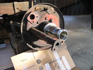
After having the left Rear Brakes open in April 2013, I knew that I needed to rebuild them as they were badly covered in oil. So Starting in December 2013 I removed the rear Shoes from both sides of the rear axle and had new Brake Pads attached. While they were off I cleaned the backing plates, renovated the right hand Rear Wheel Cylinder, painted things that needed it, then cleaned and re-greased the hubs as well as changing the Hub Oil seal.
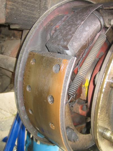
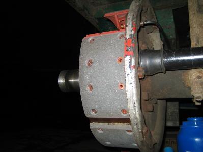
Well oiled Brake Shoes
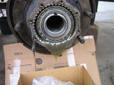
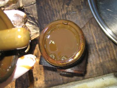
Waiting for the oily grease to leave the Hub
Everything was wet with Oil
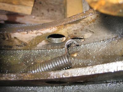
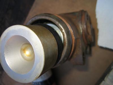
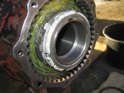
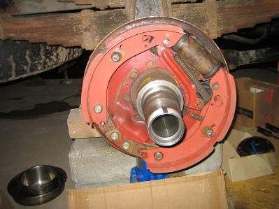
The oil fang removed and starting to clean
Wheel Cylinder well in need of attention!
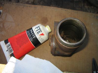
Starting the reassembly of the reamed Wheel Cylinder with a coating of brake assembly paste
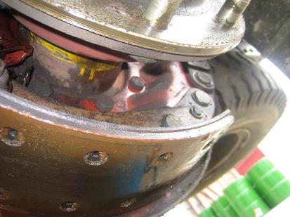
Oil has been leaking from the Wheel Cylimnder and from the Rear Hub seal to soak into the Shoes.
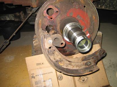
Removing the Brake components
Backing plate clear for cleaning
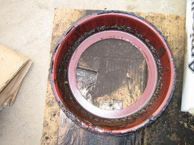
The remains of grease collected in the fang
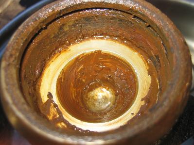
Crusts of rust
The Piston, Rubber Seal and Spring
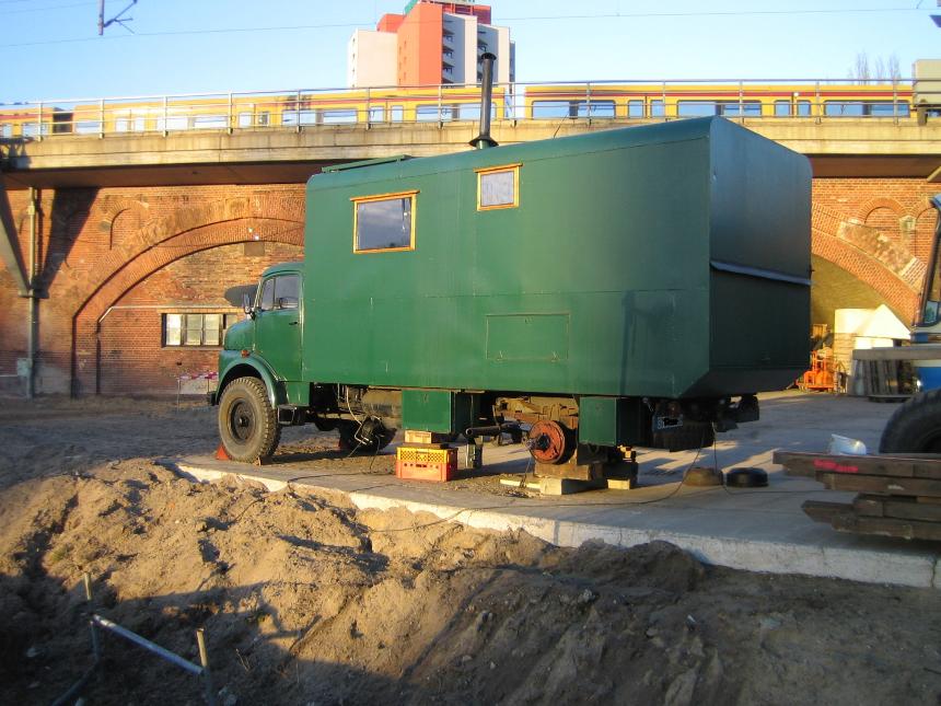
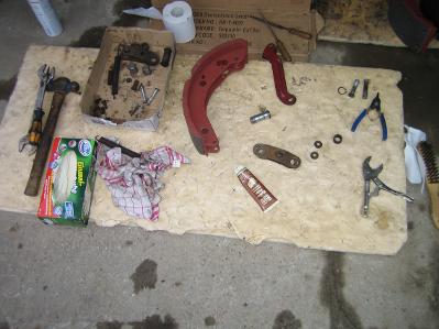
Very nice weather for doing the job
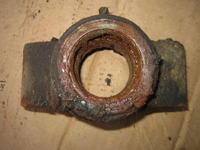
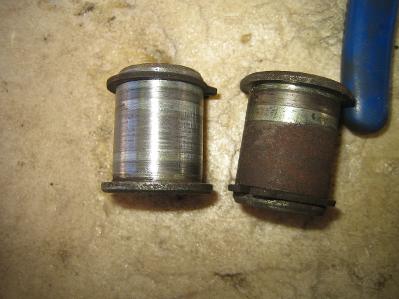
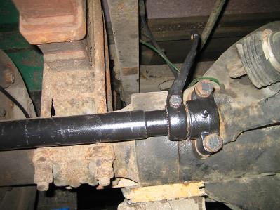
The Hand Brake Activating Shaft Bushing Holder
after removal
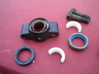
The Bushing cleaned and about to replace the Bush and new oil seal
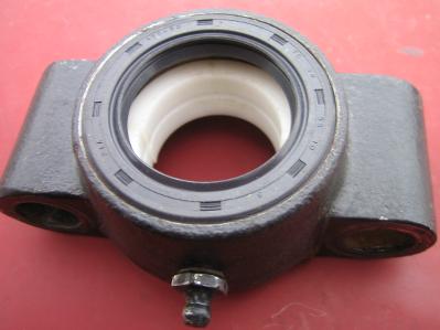
New bush in place
Before and after sanding rust off the connection pins
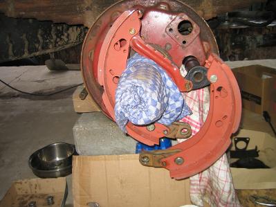
Getting the Shoes in position
New Shoes and the Hand Brake Shaft with new sealing rubber
New Grease and Hub Nuts tightened
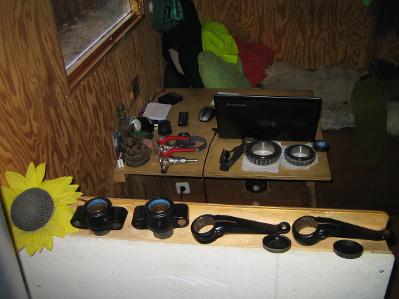
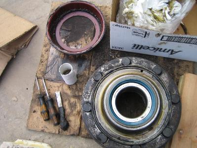
Parts claened, painted and waiting for assembly
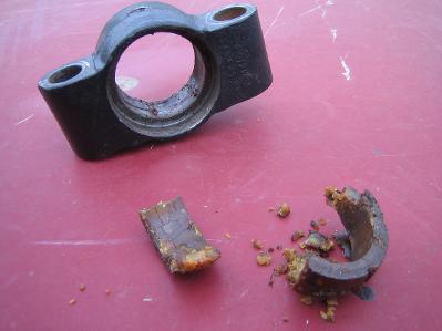
The nylon bush after 47 years was well crumbly
Starting to reassemble the Brakes
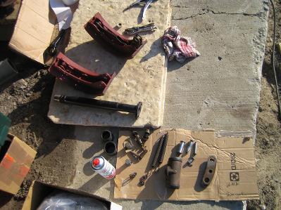
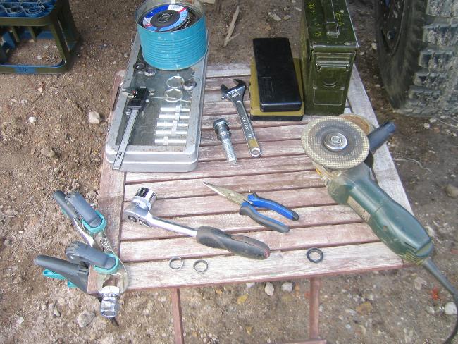
Parts laid out ready for assembly
In position and with copper paste on all moving parts
The Hand Brake Shaft held in place with the Bushing
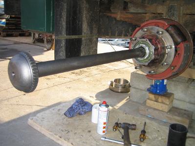
The Axle being slid in
Diesel Tanks
Due to my original round Diesel Tank being to small with a capacity of only 100 Liter, I decided to add two, 200 Liter tanks, one on each side of the Truck.
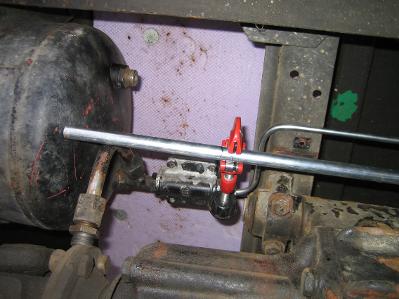
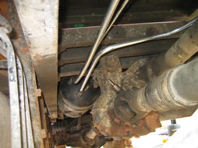
First I had to move the Air Tank as it was mounted on the left outside frame of the chassis where I wanted to mount the first new Diesel Tank.
First I had to move the Air Tank as it was mounted on the left outside frame of the chassis where I wanted to mount the first new Diesel Tank.
Moving the Air Tank
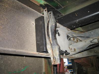
Mounting the new holders for the Air Tank
on inner side of the Chassis
on inner side of the Chassis
Cutting the pipes to fit
The tank is mounted and new air pipes are going in
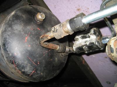
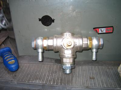
Main air feed and regulator mounted
Mounting the Diesel Tanks
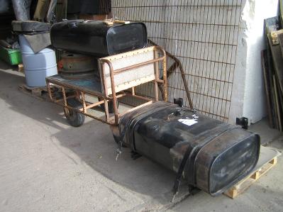
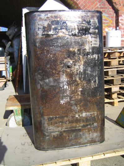
The two MAN Tanks; 1060mm L
600mm W
600mm W
360mm H
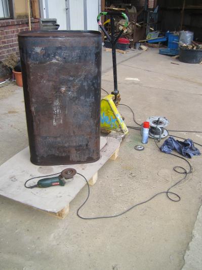
Sanding off the rust and flaky paint
I
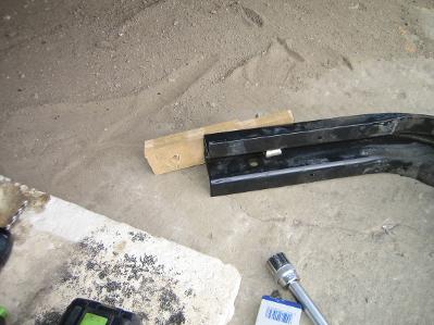
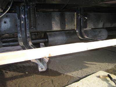
made a wooden template spacer to get the correct distance away from the
chassis to clear the Koffer suspension. Then I had steel spacers made
following the template
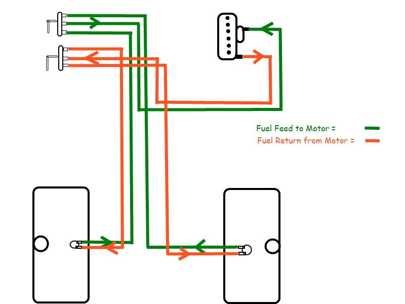
My Tank plan for the Fuel feed and return going through 3 way taps
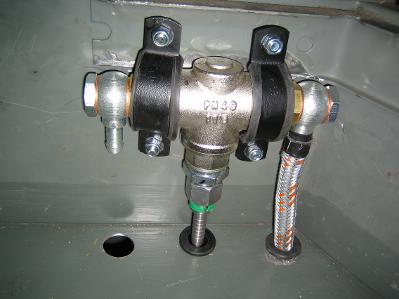
Tap mounted with fuel hose going through rubber grommets
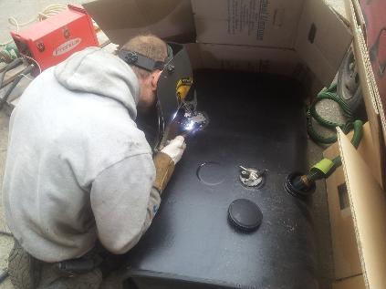
TIG
welding on the plates to hold the bolt on Fuel Gauge Sender Unit. Im
running the inert exhaust from my car into the tank so there are no
explosive gases in the tank
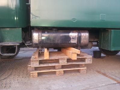
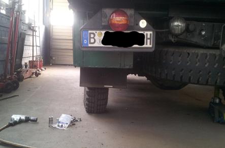
Lifting the Tank to find the right position that will clear the Koffer and give me the ground clearance that I want
Temporally bolted in place to check clearances
Cutting the mounting holes for the taps
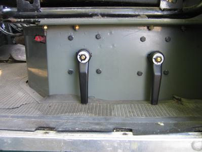
The Levers mounted on the side of Drivers Seat
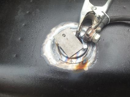
Welding almost finished. A small metal plate was put over the hole to keep most of the exhaust fumes out of the welders face
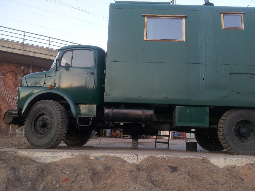
What
it looks like with the left side Tank finally mounted. Plenty of ground
clearance. A thick Aluminium plate is going to be mounted under the
Tank to protect it from damage when using the Sand Ladders
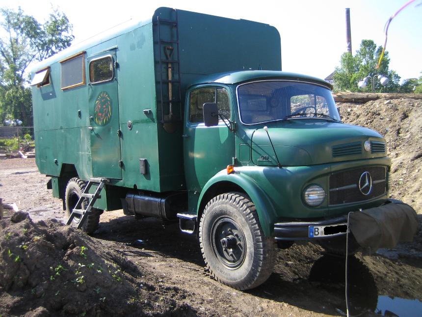
And the right side Tank is finally on. Im now able to carry a total of 400 Litres of diesel.
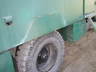
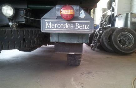
Also showing the new cut out above the Rear Wheel
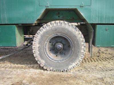
Wider Rear Rims
I bought new rims for the rear axle to get the wheels sitting in line with the edge of the Koffer.
My new Rims are 8.5V x 20 with an ET of 130mm.
My new Rims are 8.5V x 20 with an ET of 130mm.
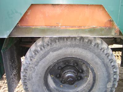
But first I needed to cut out my wheel arches as my wheels were sitting up inside them. It had been on my "To Do" list for a while as changing the rear wheels had always been a struggle to get the wheel in under the arch edge then up over onto the axle hub!
Also its going to be much easier to lift into position the 35 kg Snow Chains.
Starting to cut out the arch
All cut away. I used Gaffe Tape to close and weather proof the edges, then painted over it.
It works well
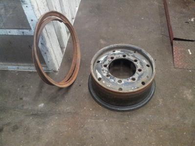
This is the old Rim. 7.5 x 20
The Wheel on old Rim
The front section is free
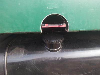
I also made this cut out to give more room for filling the Tank
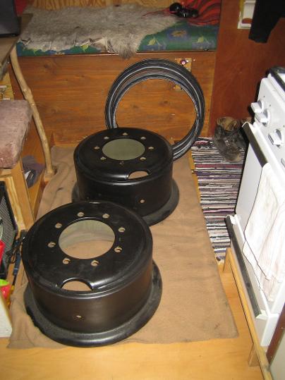
The newly painted Rims on the way to changing them over
Now sitting on the new Rim
In 2019 I bought the same Rims but with the Kugelsenkung,
so the following section is just old information
As the new Rims didnt have Kugelsenkung on the edge of the wheel bolt holes , I had to build some rings to centre the Rims. So I ground down some of the Kugelrings that were used with the Kugelsenkung system as they are made of hardened steel.
I used my flex to grind down the edge of the Kugelring while it was being held on a bolt of the same internal diameter
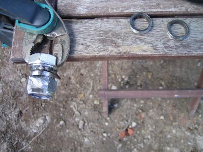
Held to my work bench while grinding
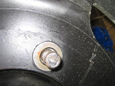
The Newly ground ring in position on the Wheel Bolt and centering the Rim
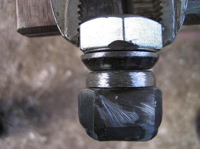
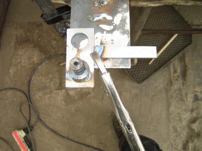
A
close up of my set up. Ive cut away part of the nut to give me more
room to hold the flex flat while grinding. As I grind the Kugelring
spins and I grind evenly around the edge
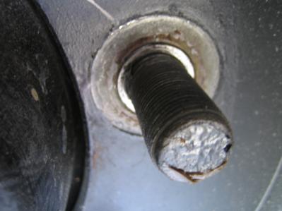
Here it can be seen how it is centering the Bolt in the middle of the Rim Bolt Hole
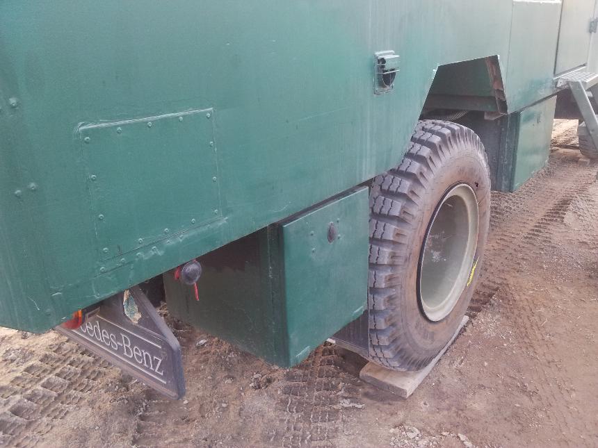
Now the wheel sits in alignment with the side of the Koffer, making me more stable off road
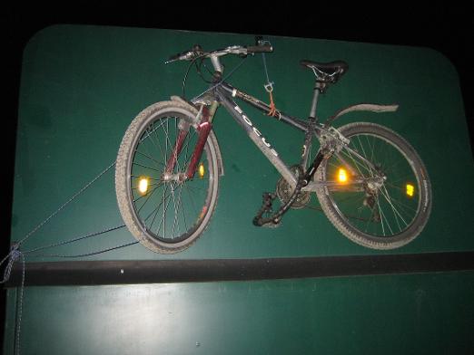
My Bike now has a place to live while on the road
Due to the new gearbox being fitted in 2017, this lever does not exist any more!!!
New Winch Lever Connection
When I mounted the Free Wheel Hubs I had to move the Speedometer cable from the front of the Transfer Box to the Gear Box. Where the speedometer cable screwed in was also screwed the shaft that connected the Lever for operating the Winch.
So I had to build a frame to hold the shaft just behind where it used to be and at the same height. I also needed to shorten and bend the final connection bar to the operating arm on the Winch Gear Box
So I had to build a frame to hold the shaft just behind where it used to be and at the same height. I also needed to shorten and bend the final connection bar to the operating arm on the Winch Gear Box
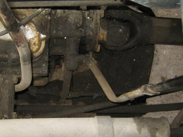
This is how the Lever used to be mounted
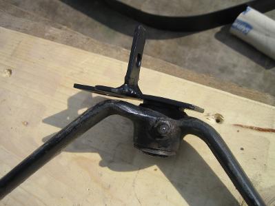
Staring to weld a frame with the offset shaft
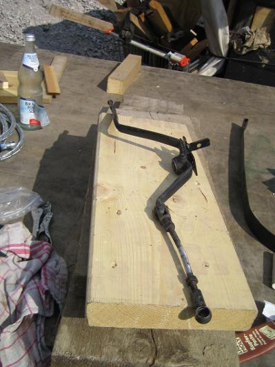
The lever with the new frame attached. The
final connection bar has already been cut and
re welded, but not yet bent
final connection bar has already been cut and
re welded, but not yet bent
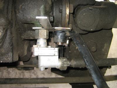
Fitted in position and checking for clearances
I was also able to connect it with a bolt that was on the to the side of the Gear Box, so welded another small tab on my frame
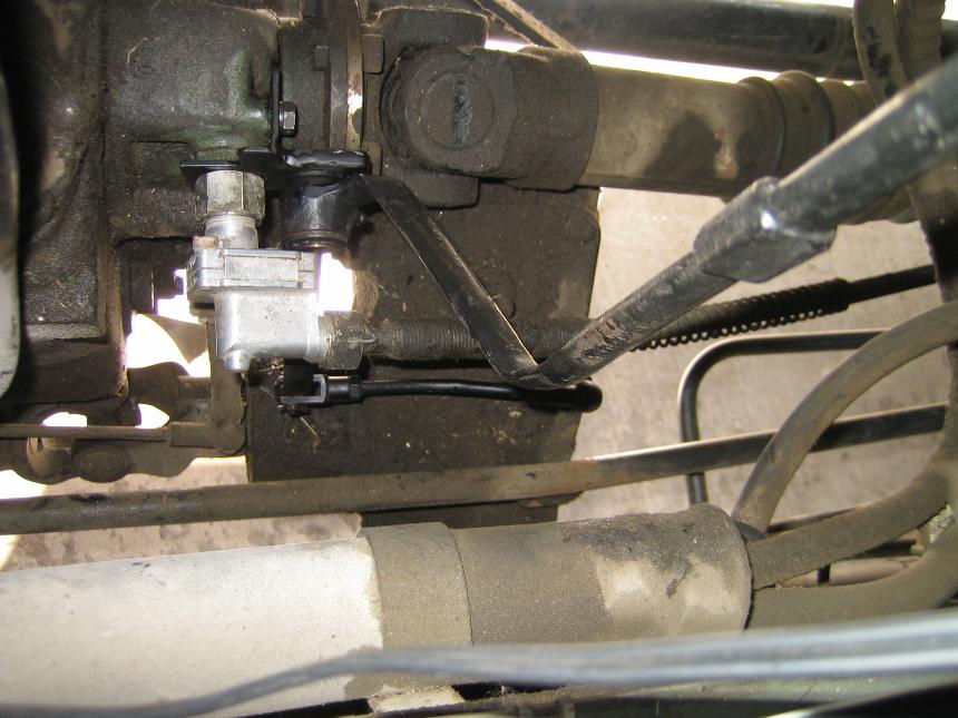
With it mounted in place the Winch is again working.
The bend in the final connection bar can now be seen
The bend in the final connection bar can now be seen