So finally got round to sorting out the electric cables that hung for so long over the Day Bed waiting to be connected into a Fuse Box. It took one day to sort out as some of my labelling had fallen off over the 3 years that it all had hung here.
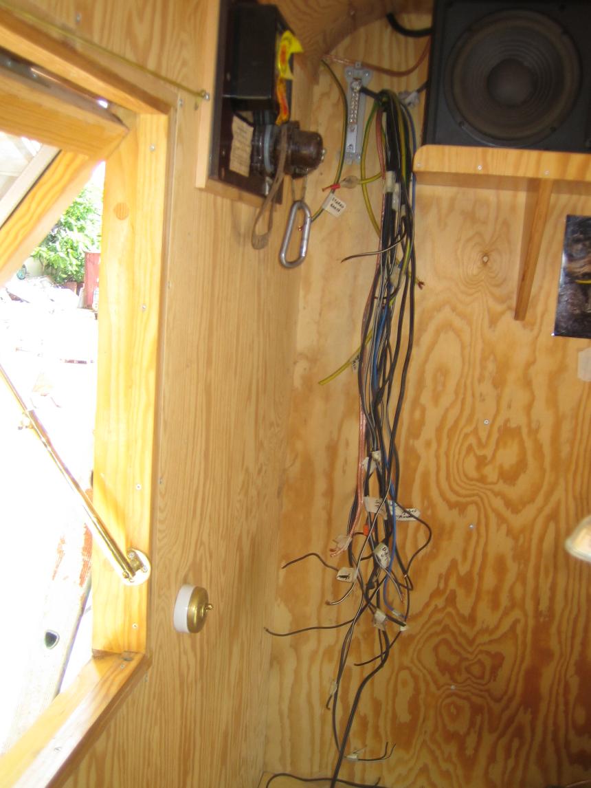
How it has been for the last 3 years with labelled cables just hanging down the wall
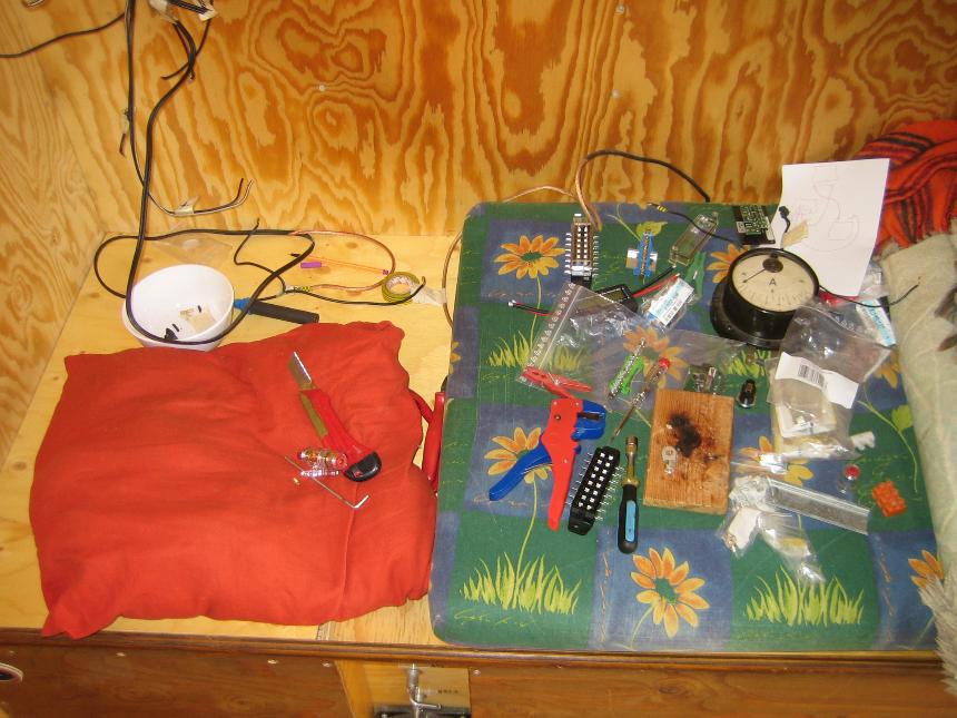
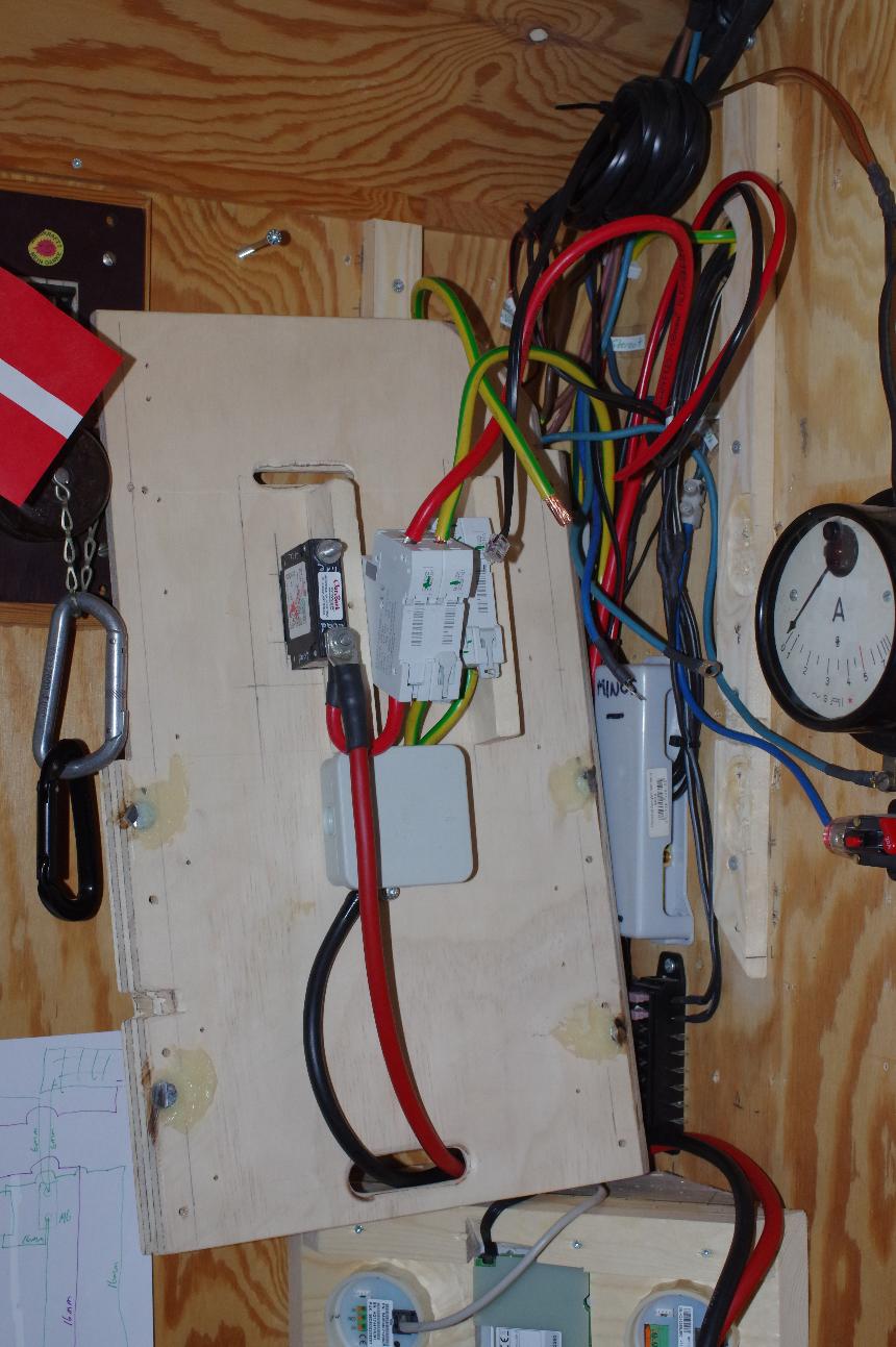
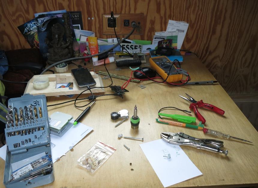
Tools and components laid out ready to hand as I use them
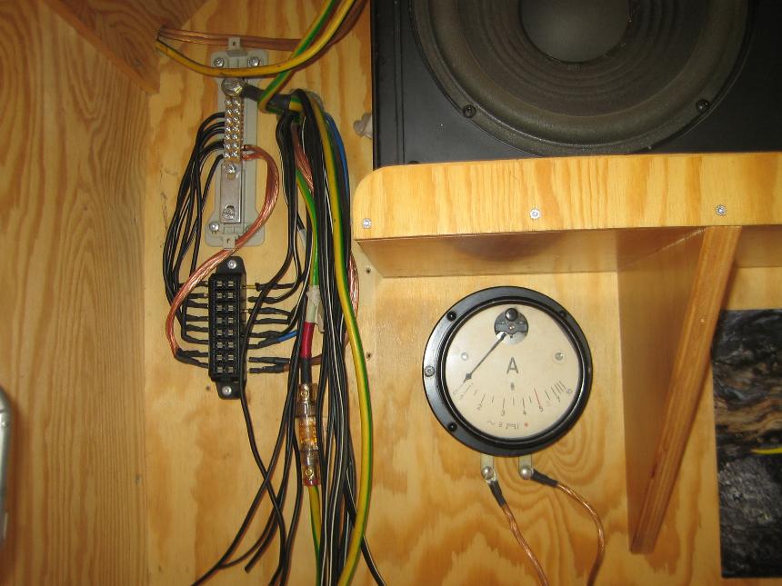
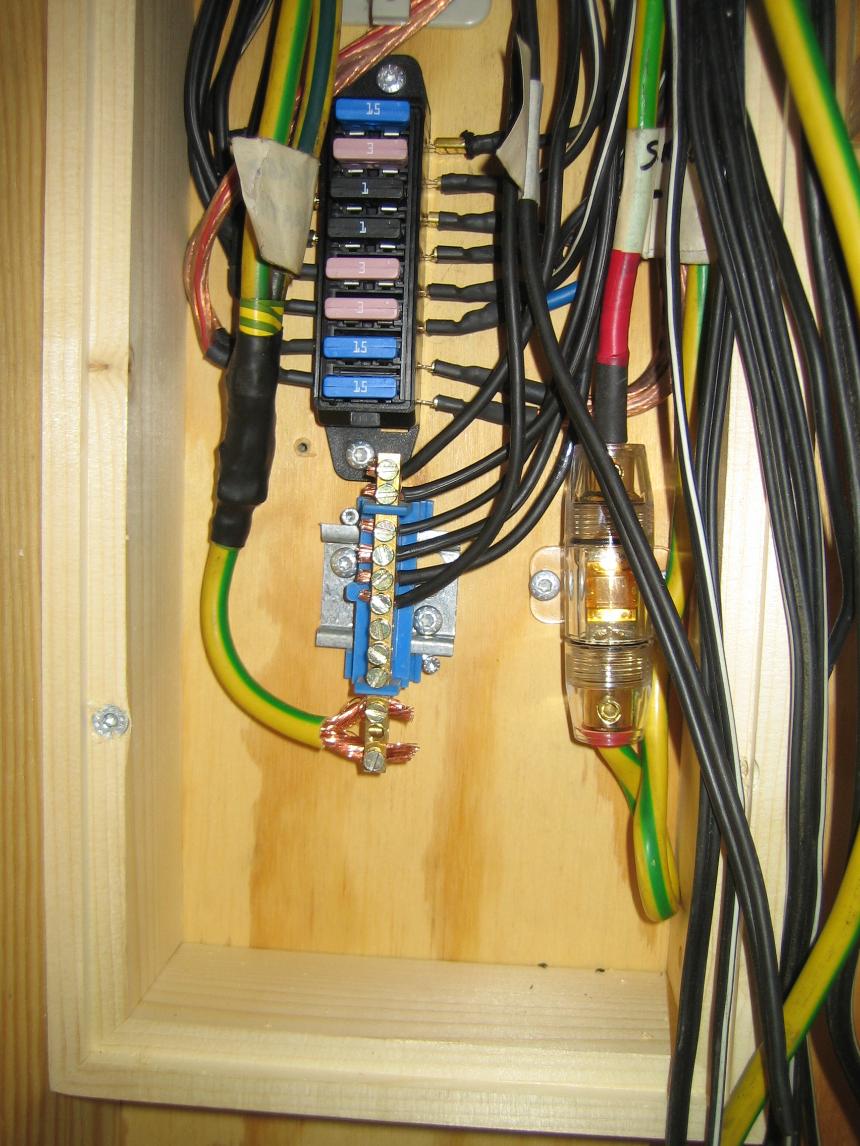
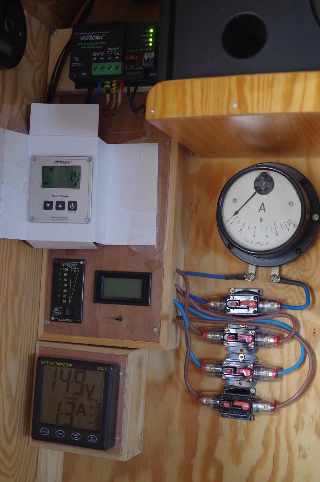
My main power feed is a 35mm2 cable
from the battery bank to a main distribution busbar that then has wires
leading down to the individual fuses. All the black wiring is from 2.5mm2 cable.
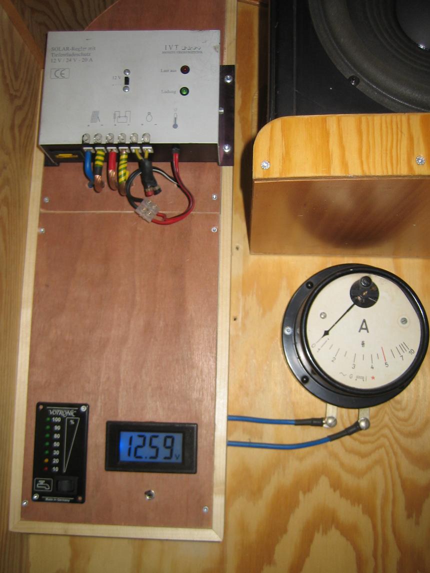
The Ammeter shows the current coming from the Solar Panels
I have put the power supply to the Stereo thru a 40A fuse and 25mm2 cable
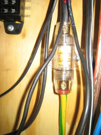
The Fuses are in and the Earth busbar mounted. 2 earth cables are soldered together as they join the stereo with the battery and the earth busbar. The surrounding box frame is now also in place.
August 2013, I finished with a Voltmeter, switchable between the two batteries and Water Tank level meter.
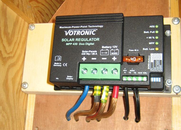
The IVT Solar Regulator above, is a Pulse Width Modulation device
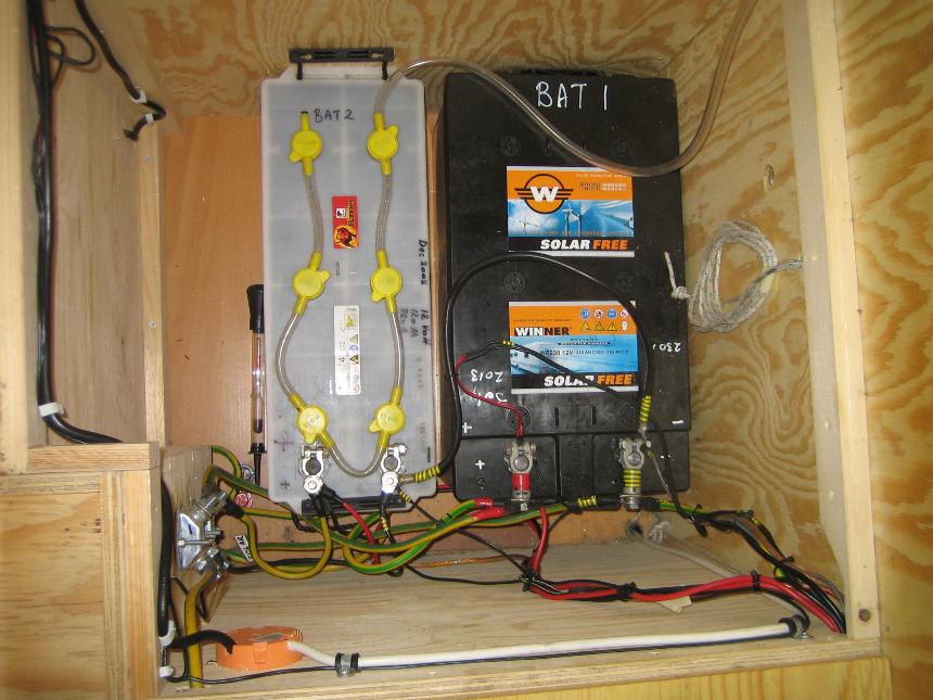
My
battery box with an old 120Ah Banner starter battery from the Truck
thats still working, and my new Winner AGM VRLA Solar Free WF 230Ah battery
I always mark my batteries with the battery details: Ah & buying date as well as clearly mark + & -
I mark all my earth (-) cables with Yellow/Green electrical tape
Positive sometimes with Red
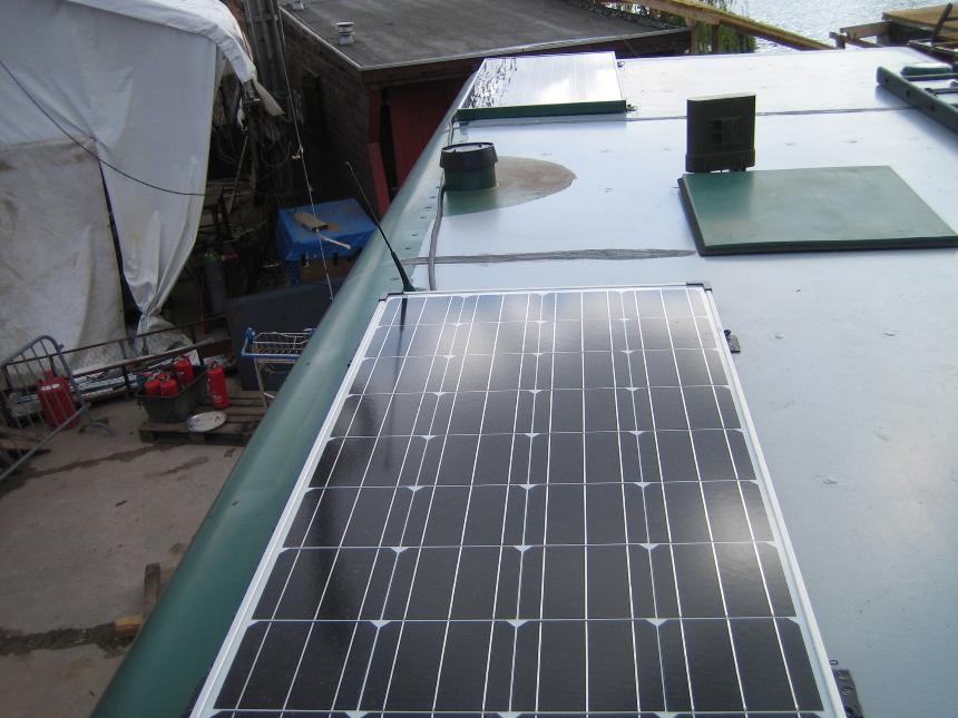
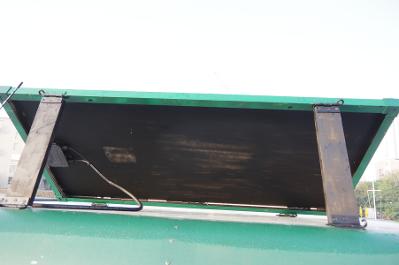
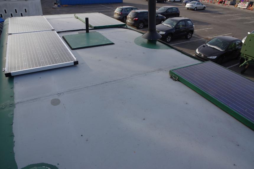
The two Solar Panels on my roof.
Also can be seen is my Powerlink Outdoor Plus WLAN Long Distance Antenna, just in front of the roof hatch.
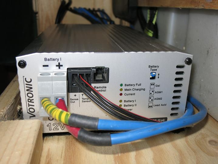
Votronic B2B Charger 1212-25 IUoU
April 2015
[As of mid 2019 the B2B has been removed
due to not driving enough and moving to a LiFePO₄ Battery]
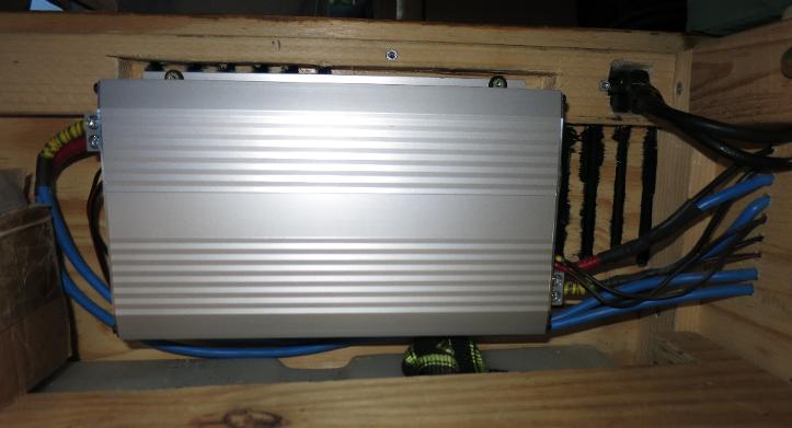
In 2015, I fitted a Votronic B2B
Charging Converter VCC 1212-25 IUoU. This allows me to charge the battery while
driving. It keeps the batteries separate and only charges the House battery
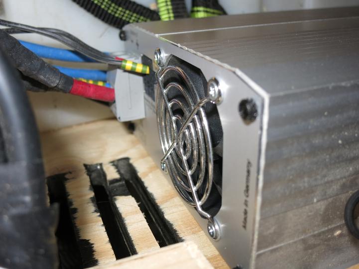
once the Truck battery is full and charged. I mounted it just above the water
tank in the compartment right beside the battery compartment, to keep the cable
length to a minimum.
Mine is 12 Volt to 12 Volt at 25
Amps.
Votronic B2B
Charging Converter VCC 1212-25
In February 2018 I put two more Solar Panels on my roof as during a winter in Danmark I am just not getting enough light.
I am going to need to add some more before next winter as I know this is still not enough.
I have room for three more on the roof but will probably need to make something on the ground to hold some of them.
Now have four Solar Panels on the roof
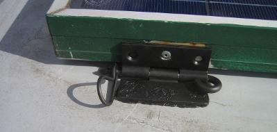
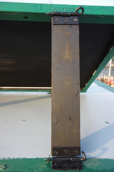
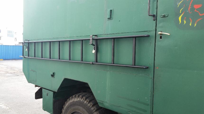
I had to remove my ladder to make room on the roof. So I built a lockable holding rack on the side of the Truck.
I
have now run the Solar Panels through 40A switchable fuses (about to by
replaced with 20A) so I am able to isolate each panel as I need.
These fuses are really low quality from China, and I used them only for one year before changing everything again.
I would not recommend putting any serious current flow through them. Im only putting max 9A through each one.
Also
I bought a Solar Computer for the Charge Controller so I can monitor
how much Solar I receive each day. It is at the moment temporarily
mounted until I get the time to set it into the wood.
Also can be seen is the Battery Monitor for keeping track of the battery capacity.
New Solar Panels & Victron MPPT Charger
November 2018
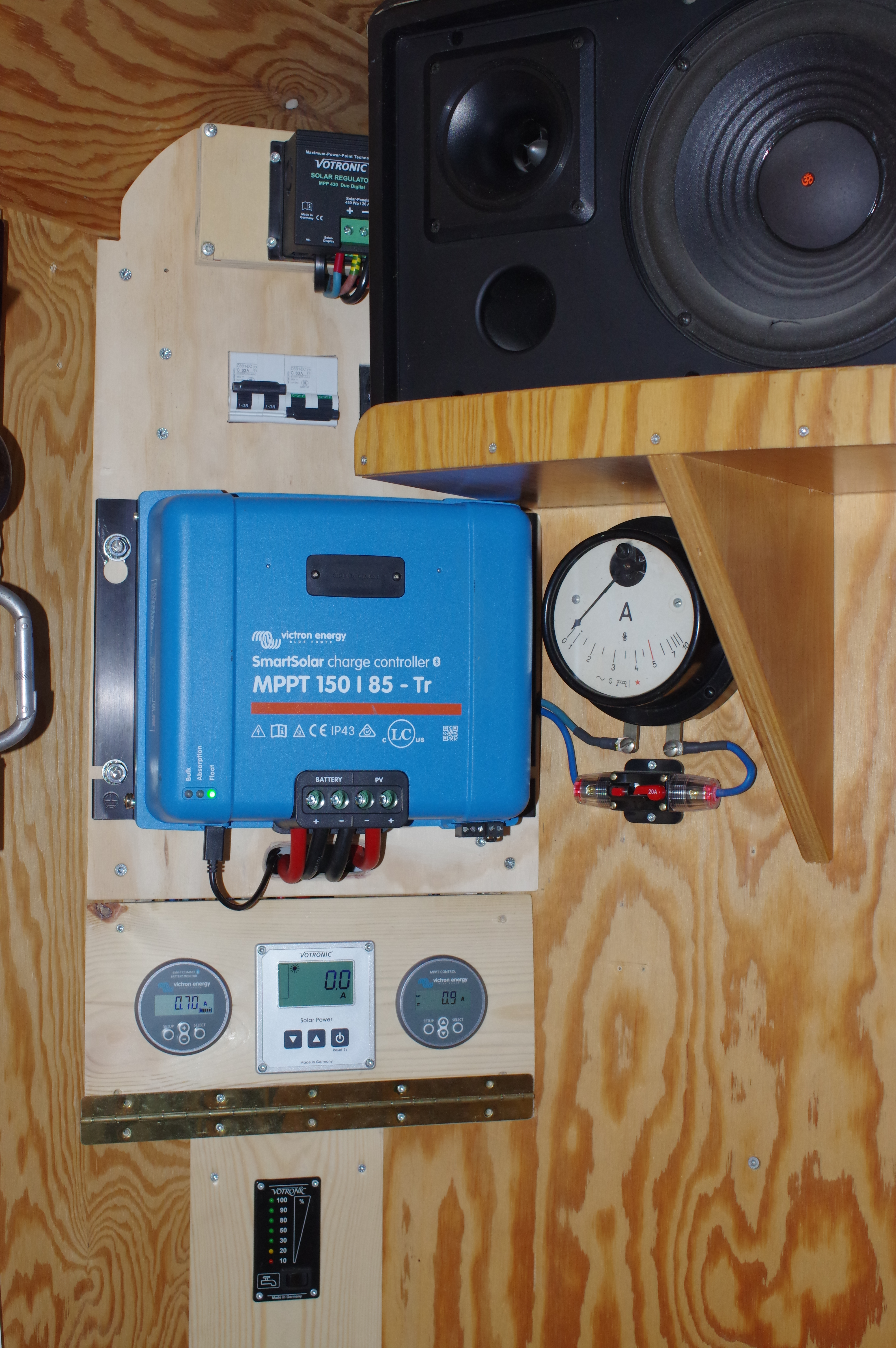
So in November 2018 I added another 150W Monocrystalline Solar Panel to the roof and rewired my complete electrical fuse box, then put in a new Victron Smart Solar Charge Controller MPPT 150/85 TR.
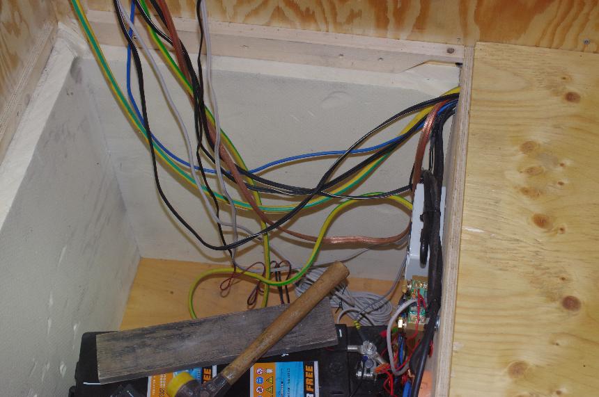
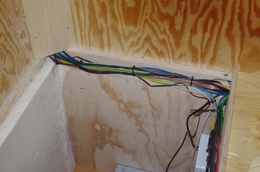
I used to have the wires running up behind the wall to the fuse box, so these I pulled out and they now run up the corner of the house behind a board so I can get to them and add more if needed.
I also insulated the battery box with another layer of 50mm Styrodur to both outside facing walls.
Here can be seen the two new 50mm Styrodur pieces before I faced them with plywood and the newly run cables hanging down the wall.
Now one board is on and Ive got the tidy cables laying along the top out of the way
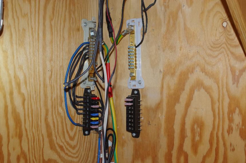
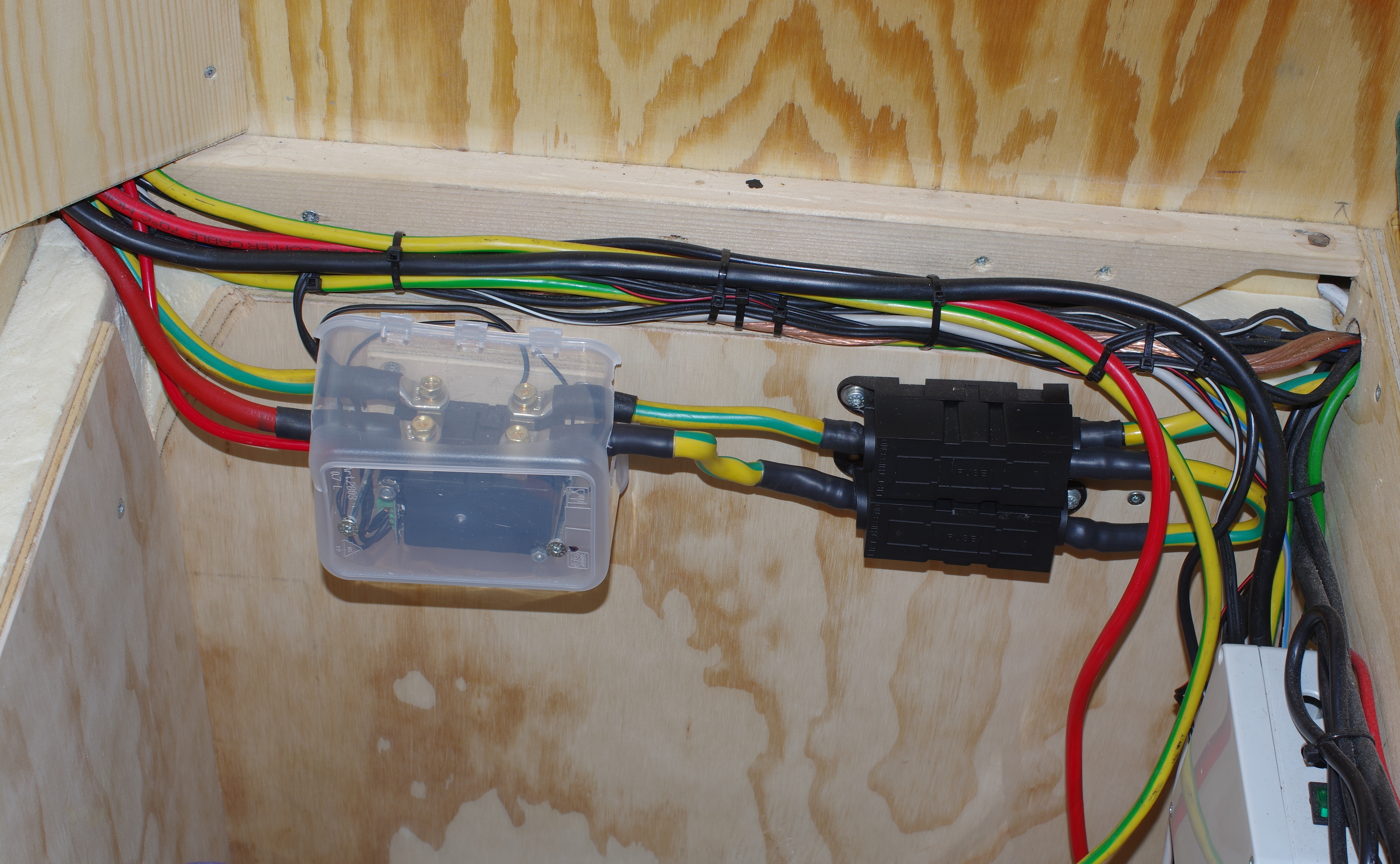
Starting to put in the new "Plus" & "Minus" Busbars and the fuse holders
Glued and screwed mounting rails for the new board and have most of the wiring finished and cable tied in order.
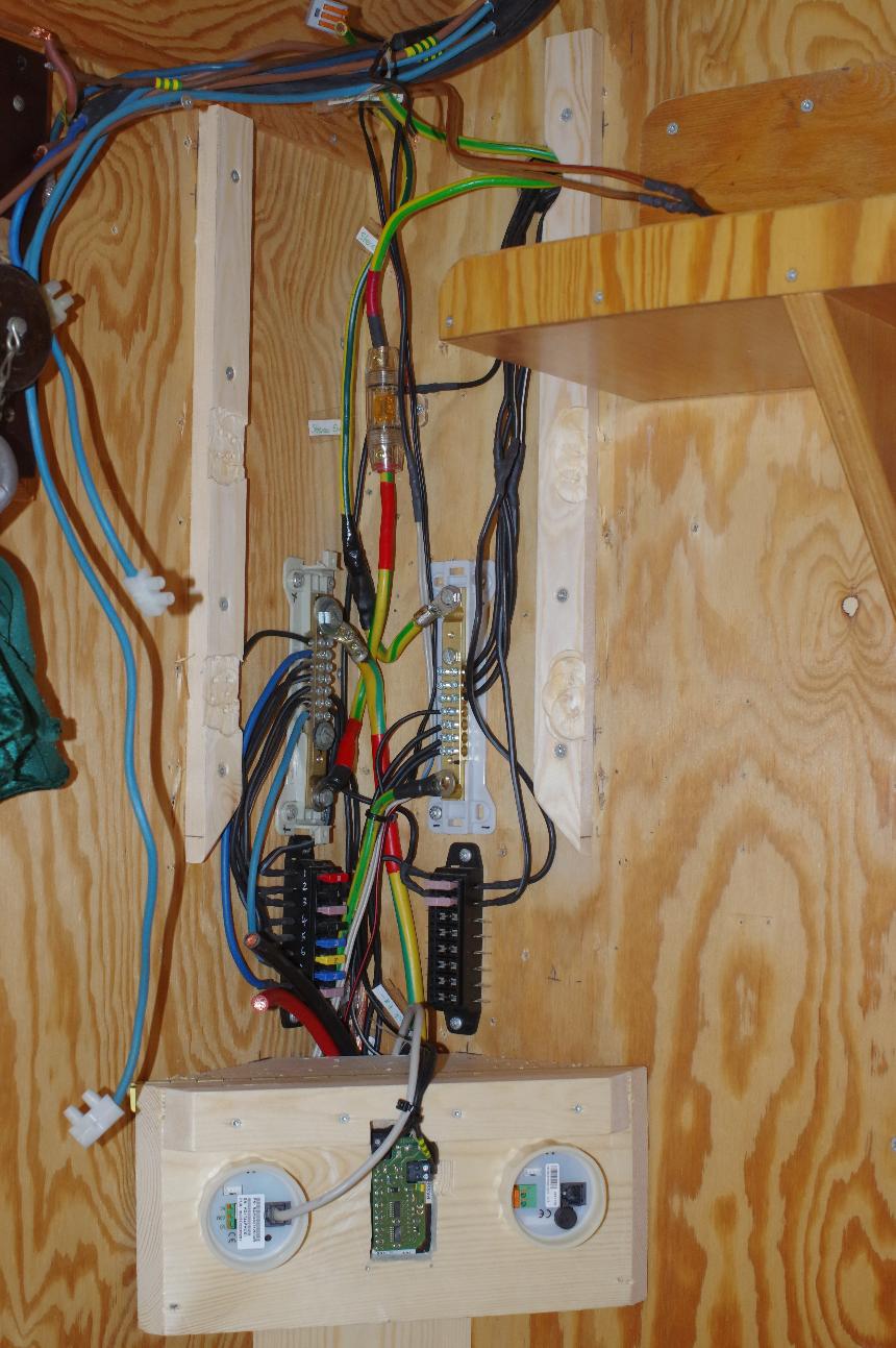
The tip down front will give access to the fuses as well as hold the Victron Smart Battery Monitor 712, Victron MPPT Control and my Water Gauge.
The Water Gauge later gets moved and the monitor from the Votronic LCD-Solar-Computer goes in the middle.
On the left are two 120A Latching Relays for the High Voltage Cutoff and Low Voltage Cutoff as well as new Main fuses.
I will later be putting in a LiFePO₄ Battery system, so Im setting every thing up for that now.
The backing board is about to be mounted
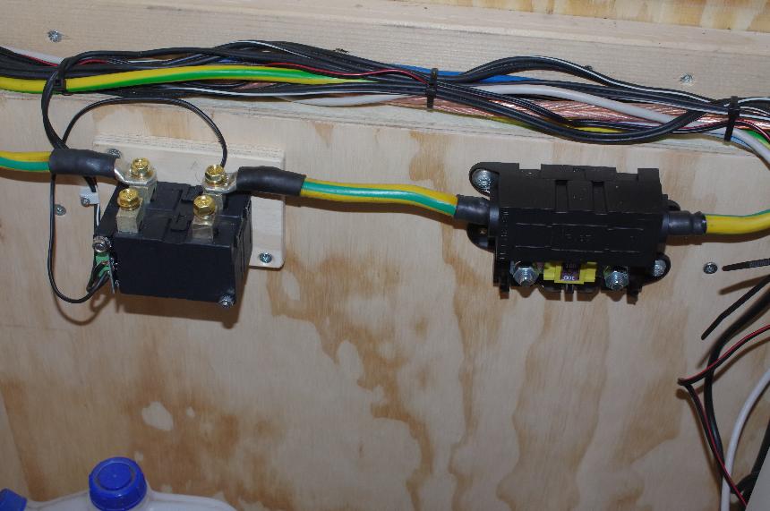
Ive got the DC Circuit Breakers set in place and about to wire them in.
The black Circuit Breaker switches the + from the Solar Panels, which is input as 2 in series then 2 in Parallel.
One of the white Circuit Breakers will be used to disconnect the Solar - input to the MPPT
The other two breakers then switch the MPPT input + & - to a Power Supply for charging when Solar is not available and I need to charge the battery.
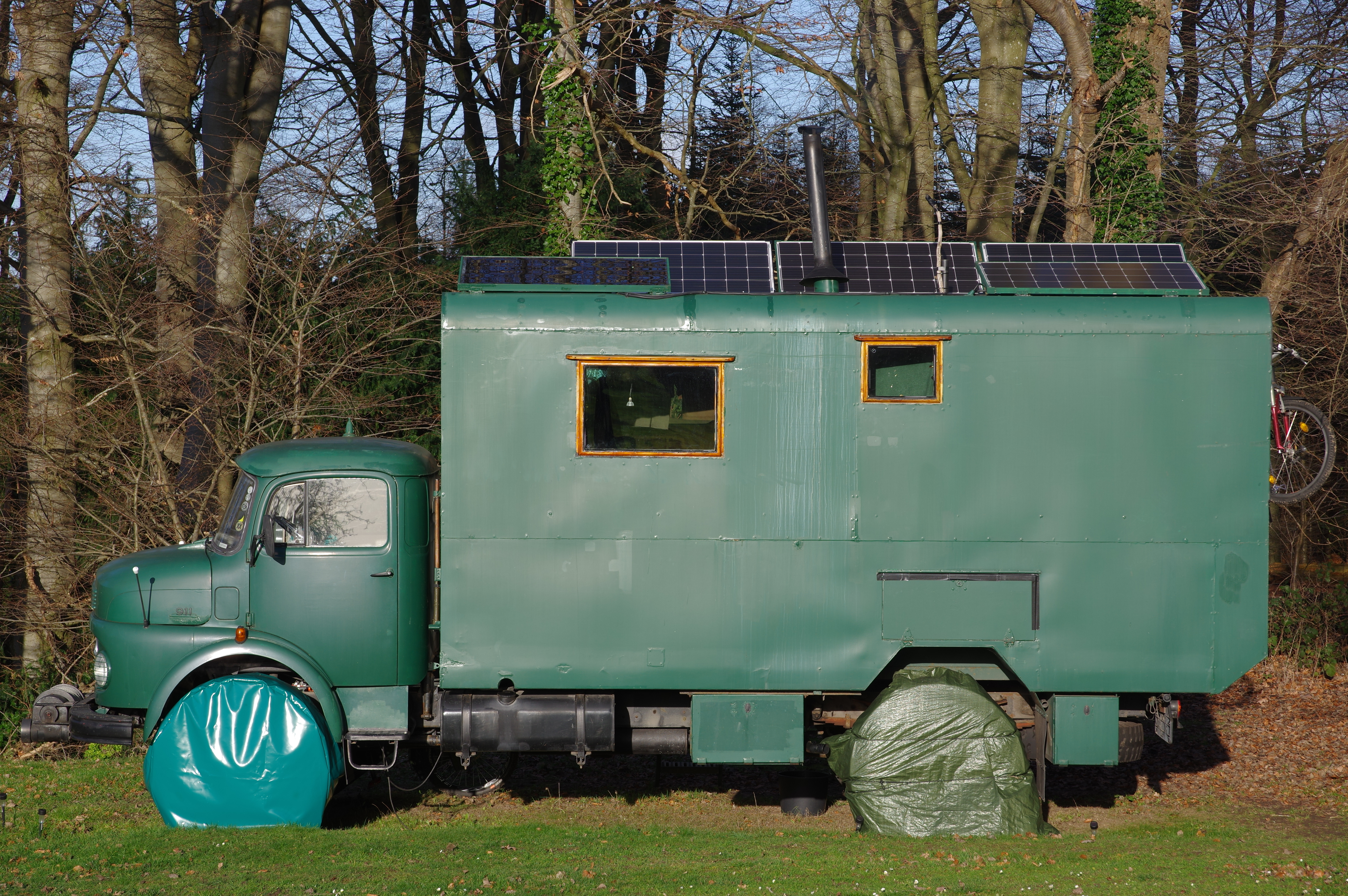
Truck with 5 Solar Panels on the roof giving total capacity of 700Watt
Fyn, Danmark, Dec 2018
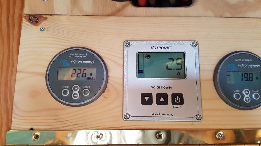
22.6A going into the Battery, Fuck Yeah !!!
And that is 11 February 2019, Danmark Winter sun, going in !
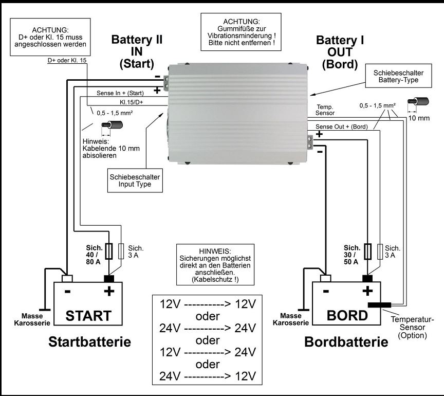
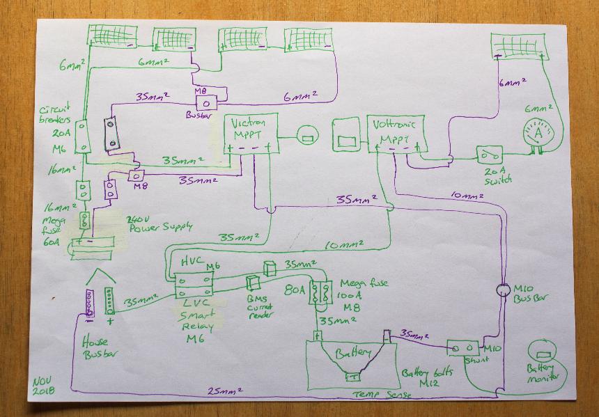
My wiring diagram for the Project!
Nov 2018 MkI
Battery box with Latching Relays in place but not set to cut off. Plastic cover screwed over the contacts to prevent short circuit.
Latching Relays will be wired into the LiFePO₄ cells BMS once I finally get around to putting it in.
Now just waiting for me to install in the future the LiFePO₄ cells to make the Battery as my AGM is on its last legs!
Remote Switch for Inverter
March 2019
Every time I needed to use my Inverter I used to have to open the top of the Day Bed bin.
So I was rather happy when I got my new Victron Phoenix Inverter 350, to find that it has a connector for a remote turn on.
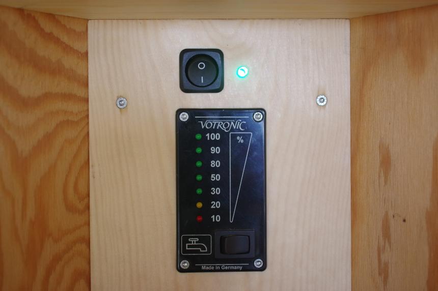
Of course that meant out with the tools to put in a switch and a LED light, so I can remotely turn my Inverter on and off
Selecting a Green LED and some Resistors to wire in beside the Switch
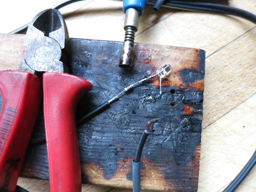
Soldering the Resistor to the LED and the lead wire
Bare wires and the Resistor covered in shrinky as I fit the Switch and LED in position
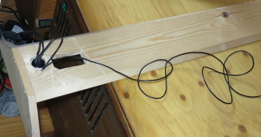
Just starting to connect the wires together for the Switch into the rear of the Inverter
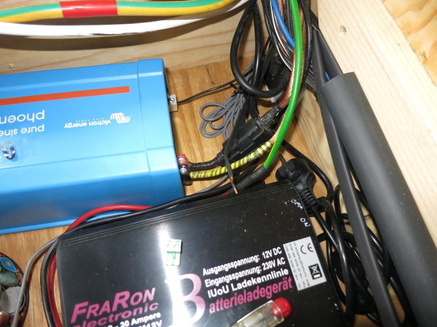
The Victron Phoenix Inverter 350 is sitting in the Day Bed bin on top of a board placed above the Water Tank
Beside it sits the 30A, 230V → 12V Battery Charger from FraRon
The Remote had a small link wire that I have stuck with tape to the top of the Inverter, as the switch replaces it
All up and working well. So much easier now to turn on and off, especially when using the Printer